| RETURN | Multiplexing |
North American T1 Facilities
North American T1 facilities operate at 1.544 MBPS. Framing may be either Superframe (D4) or Extended Superframe (ESF).
These facilities are deployed in the United States, Canada, Korea, Taiwan, and Hong Kong (Hong Kong also employs International G.732 inter-connectivity).
Related Specifications:
AT&T Pub 62411 (D4, Line Characteristics)
AT&T Pub 54016 (ESF)
ANSI T1.403 (DS1 Metallic Interface)
Superframe Format (D4 Framing)
The standard frame is 193 bits long (1 Framing bit + 24 8-bit timeslots). Each timeslot is scanned at a rate of 8000 times per second. Therefore, in one second, there are: 8000 * 8 bits/TS * 24 TS = 1,536,000 Bits of “Payload” data transmitted. There are: 8000 * 1 = 8,000 Bits of synchronization bits transmitted within a one second interval. Therefore, the total aggregate rate of the T1 signal is 1,544,000 BPS (1.544 MBPS).
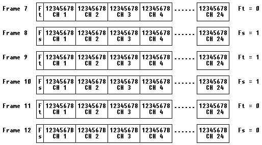
A Superframe consists of twelve 193-bit frames. A framing bit can support different functions, depending upon which of the twelve frames it is in. There are two types of framing bits; Terminal framing (Ft) and Signaling framing (Fs) bits.
Frames 1 through 6:

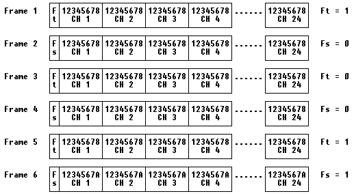
Frames 7 through 12:

D4 Voice and Data Signaling
The transport of signaling states is required in Switched voice or data (Switched 56K service). Signaling is accomplished through a “Robbed Bit” method where bit 8 of each channel’s timeslot is “robbed” to indicate a signaling state in the 6th and 12th frames. Effective throughput for the A signaling bit (Frame 6) is 666.66 BPS. Effective throughput for the B signaling bit (Frame 12) is the same (666.66 BPS).
Extended-Superframe Format (ESF)
The standard frame is 193 bits long (1 Framing bit + 24 8-bit timeslots). Each timeslot is scanned at a rate of 8000 times per second (as in D4/SF). The line rate is 1.544 MBPS supporting a data “payload” of 1.536 MBPS.
There are three types of framing bits; Frame Pattern Sync (FPS), Datalink (DL), and Cyclic Redundancy Check (CRC) bits. Of the 8 KBPS framing bit bandwidth:
4 KBPS is allocated to the Datalink
2 KBPS is allocated to the CRC-6 character
2 KBPS is used for synchronization purposes
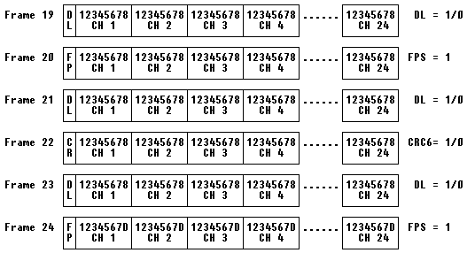
An Extended Superframe consists of twenty-four 193-bit frames.
Frames 1 through 6:

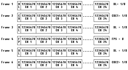
Frames 7 through 12:

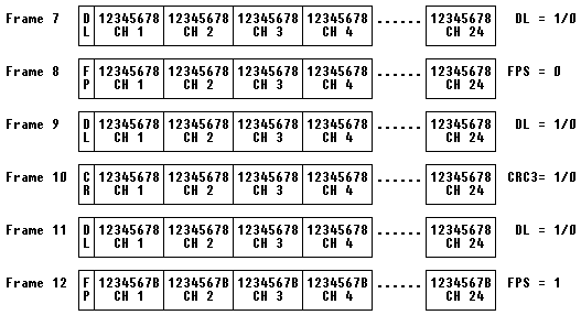
Frames 13 through 18:

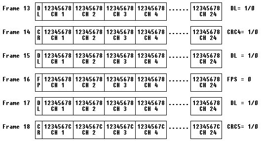
Frames 19 through 24:

ESF Voice and Data Signaling
The transport of signaling states is required in Switched voice or data (Switched 56K service). Signaling is accomplished through a “Robbed Bit” method where bit 8 of each channel’s timeslot is “robbed” to indicate a signaling state in the 6th, 12th, 18th, and 24th frames. Effective throughput for the A signaling bit (Frame 6) is 333.33 BPS. Effective throughput for the B, C and D bits is the same (333.33 BPS).
ESF Datalink Types
Operation of the ESF datalink depends upon whether the AT&T TR 54016 or the ANSI T1.403 version of ESF is implemented by the carrier. The two standards are very similar; the only significant difference being in the implementation of the ESF Datalink Framing Bits.
AT&T TR 54016
AT&T TR 54016 calls for used of a simplified X.25 Level 2 structure, known as Telemetry Asynchronous Block Serial Protocol (TABS). This protocol consists of the following fields:
- – Flag (hex “7E”) – Address (single byte)
- – Control (single fixed byte: 00001000)
- – Information Field (variable length)
- – FCS (Frame Check Sequence)
ANSI T1.403
The ANSI T1.403 specification can use Bit-Oriented-Signals (consisting of two bytes each) on the datalink OR Message-Oriented-Signals. Bit-Oriented-Signals consist of an all-ones byte, followed by a ZERO BIT, followed by a six bit identifier, and the last bit set to a ZERO. An example of a Bit-Oriented-Signal is the 00000000 11111111 code used by ESF as a Yellow Alarm condition.
However, ANSI has also defined 16-bit words to indicate Payload/Line loopback Activation/Deactivation, Automatic Protection Switching (APS) Line Switch Commands, APS Line Switch Acknowledgements, and APS Line Release commands.
The ANSI T1.403 Message-Oriented-Signals conform to the LAPD, Q.921 HDLC format:
- – Flag (hex “7E”) – Address (2-Bytes used to express SAPI, TEI information)
- – Control (single fixed byte: 00000011)
- – Information Field (variable length)
- – FCS (Frame Check Sequence)
ANSI T1.403 terminal equipment (CSU) transmit Performance Report messages towards the network every second. The following Error Events are reported in the Performance Report Message:
T1.403 CRC Errors
This error event occurs when the received CRC code does not match that CRC code calculated locally.
T1.403 Severe Errors
This event occurs when two or more framing bit errors are detected in any 3 mS window. Alternatively, existing 2 of 4, 2 of 5, or 3 of 5 errored framing bit criteria can be used to declare a Severe Error (SE). When a Severe Error is reported, the FE (Frame Bit Errors) count is set to 0.
T1.403 Frame Bit Errors
This event occurs whenever an incorrect or unexpected framing bit is received. When a FE error count is transmitted, the Severe Error (SE) count is set to 0.
T1.403 Line Code Violations
This event occurs whenever an invalid line violation (bipolar violation) occurs.
T1.403 Controlled Slip Events
This event occurs when frames are repeated or deleted at the receiving terminal to compensate for clocking differences between the Carrier and the Terminal equipment.
D4 and ESF Alarm Conditions
AIS (Alarm Indication Signal) CFA
The AIS is also known as a “Keep Alive” or “Blue Alarm” signal. This consists of an UNFRAMED all-ones signal sent to maintain transmission continuity. The AIS CFA signal is declared when both the AIS state and RED CFA persist simultaneously.
OOF (Out-Of-Frame) Condition
Occurs whenever Network or DTE equipment senses errors in the incoming framing pattern. Depending upon the equipment, this can occur when 2 of 4, 2 of 5, or 3 of 5 framing bits are in error. A reframe clears the OOF condition.
Red CFA (Carrier Failure Alarm)
Occurs after detection of CONTINUOUS OOF condition for 2.5 seconds. This alarm state is cleared when no OOF conditions occur for AT LEAST 1 second. Some applications (AT&T DACS services) may not clear the CFA state for UP TO 15 seconds of NO Out-Of-Frame occurences.
Yellow CFA (Carrier Failure Alarm)
When a Terminal/Network equipment enters a RED CFA state, it transmits a “Yellow Alarm” in the opposite direction.
A Yellow Alarm is transmitted by setting Bit #2 of each timeslot to a 0 (zero), SPACE state for D4 Framed facilities. For ESF facilities, a Yellow Alarm is transmitted by sending a repetitive 16-bit pattern consisting of 8 MARKS (1) followed by 8 SPACES (0) in the Datalink bits. This is transmitted for a MINIMUM of 1 second.
For D4 facilities, the minimum Yellow Alarm detection time is 335 mS. Trunk conditioning should occur within 335 to 1000 mS. For ESF facilities, the MINIMUM detection time is 28 mS.
NOTE: 335 mS equates to 2680 D4-type frames.
LOS (Loss Of Signal)
A LOS condition is declared when no pulses have been detected in a 175 +/- 75 pulse window (100 to 250 bit times).