| RETURN | LANs and Novell |
The Physical Interconnection
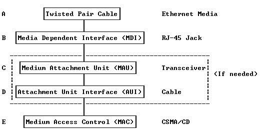
The following diagram depicts the physical interconnection of a PC (Workstation) to the Ethernet LAN:


Functional Overview
⊕ Twisted pair cable is used as the transport media. This is known as a Type “10BASE-T” Ethernet. In these configurations, each station (PC) is connected to a central “repeater” or “hub” (Star Network). The cable length may be up to 100 meters when Category 3 cable is used.
⊕ Items C and D (MAU and AUI) are associated with a “Transceiver”, if applicable. Usually, these functions are onboard the Ethernet board in the PC and no Transceiver is required.
Typical pinouts for the RJ-45 jack are:
1 = DTE Transmit Data (+)
2 = DTE Transmit Data (-)
3 = DTE Receive Data (+)
6 = DTE Receive Data (-)
Typical Transceiver pinouts are:
1 = Collision Shield
2 = Collision (+)
3 = Transmit (+)
4 = Receive Shield
5 = Receive (+)
6 = Power Return
7 = Not Used
8 = Not Used
9 = Collision (-)
10 = Transmit (-)
11 = Transmit Shield
12 = Receive (-)
13 = +12 VDC
14 = Voltage Shield
15 = Not Used
⊕ Item E, the MAC (Media Access Control) function resides onboard the Ethernet card. MAC operation controls the electrical functions associated with Carrier Sense Multiple Access (CSMA)/Collision Detection (CD) and the output/decoding of Manchester-coded 10 MBPS Ethernet HDLC frames.
A Typical Ethernet Frame
A typical Ethernet frame will look something like this:

