| RETURN | ISDN Technology |
The BRI U-Interface
BRI U-Interface Line Coding
The objective of BRI ISDN is to deliver full-duplex 160 KBPS signal over existing cable facilities. There are two modulation methods that can be used to deliver the U-Interface signals over an ordinary copper pair. However, for both modulation schemes, loading coils (which restrict the frequency response of the line) must be removed.
- 2B1Q Line Coding2B1Q coding is the standard used in North America. 2B1Q means that two bits are combined for form a single Quaternary line state. 2B1Q combine two bits at a time to represent one of four amplitude levels on the line. The baud rate, therefore, is 80 KBaud. It operates with a maximum frequency range of 40 KHz.2B1Q coding is defined in ANSI T1.601 and ETR 080, Annex A. It can operate at distances up to about 18,000 feet (5.5 KM) with loss up to 42 dB. An internal termination impedance of 135 ohms is presented to the line at each end of the U-interface. Echo cancellation techniques allow full-duplex operation on the line.2B1Q transmission can be simply described as an amplitude modulation scheme for DC pulses as indicated in the diagram below.


- 4B3T Line Coding4B3T is a standard used in Europe and elsewhere in the world. 4B3T is a “block code” that uses Return-to-Zero states on the line. 4B3T combines 4 bits to represent one “ternary” line signal state. The baud rate is 3/4ths of the data rate (120 KBaud).4B3T is defined in ETR 080, Annex B and other national standards, like Germany’s 1TR220. 4B3T can be transmitted reliably at up to 4.2 KM over 0.4 mm cable or up to 8.2 KM over 0.6 mm cable. An internal termination impedance of 150 ohms is presented to the line at each end of the U-interface. Echo cancellation techniques allow full-duplex operation on the line.In 4B3T coding, there are three states presented to line: a positive pulse (+), a negative pulse (-), or a zero-state (no pulse – 0). An analogy here is that operation is similar to B8ZS or HDB3 in T1/E1 systems, except that there is an actual gain in the information rate by coding 16 possible binary states to one of 27 ternary states.
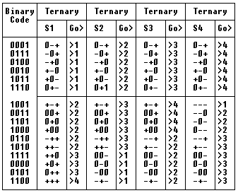
There are many ways to perform this conversion, but BRI standards define a a code known as MMS43 (Modified Monitoring State 43).


One of the requirements for line transmission is that there should be no DC build-up on the line, so there are some code substitutions based upon the transmission of the previous bits. These are indicated in the lower half of the table above. The next state (S1 – S4) to be transmitted is indicated in the column labled Go. In the table above, the left-most bits and pulses are transmitted first.
The diagram below indicates a binary code of 1100 transmitted first (State S1). Then a squence of 1101 is transmitted (using State S4).


BRI U-Interface Line Framing
-
- 2B1Q Lines
Basic Rate ISDN leaves a telephone central office on a single pair of wires. The transmission data rate of the BRI line is 160 KBPS – the two 64 KBPS “B-Channels”, the 16 KBPS “D-Channel”, and 16 KBPS of framing and synchronizing bits (Barker Code). By using 2B1Q coding, the data baud rate is 80 Kbaud.
First, a data block is formed from the 2B + D data (18 bits):


The data block is applied to a scrambler function (as in most modern modems), and converted to 108 Quat (2B1Q) symbols.
A 9 Quat (18 bit) Synchronization Word is applied, along with a 3 Quat (6 bit) Maintenance Field, to form a single Frame.
8 frames make up one Superframe. The Synchronization Word in the first frame is inverted to delineate the start of the Superframe.


Notes:

1) Frame is 240 bits (120 Quaternary Symbols) long.
2) There are 8 Frames in a Superframe.
3) Sync pattern is: -3-3+3+3+3-3+3-3-3 (inverted) in the 1st frame.
                    000010101000100000
4) Sync pattern is: +3+3-3-3-3+3-3+3+3 (normal) in frames 2-8.
                    101000000010001010
5) The Maintenance field contains a CRC error-check fields and an Embedded
   Operations Channel (EOC), used for loopback testing.
-
- 4B3T Lines
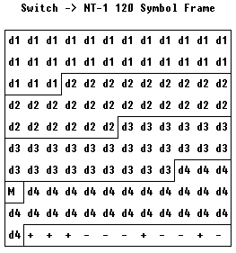
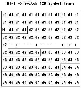
4B3T transmits a data rate of 160 KBPS at a baud (symbol) rate of 120 Kbaud by using 4B3T coding (- 0 +).
First, a data block of 36 bits is scrambled using the self-synchronizing 23-bit scrambler described in ITU Recommendation V.29. The data block of 36 bits is then converted to a data block of 27 Ternary symbols.
Four data blocks, labeled d1-d4, (108 Ternary symbols) are combined with a Sync Word consisting of 11 Ternary symbols (Barker code) and a Maintenance Word consisting of 1 Ternary symbol. This group of 120 Ternary symbols comprises the overall frame.
There is a difference in frame construction depending upon whether the frame is sent from the Switch to the NT-1 or from the NT-1 to the Switch. The synchronization characters are different and offset by 60 symbols.


