| RETURN | Trunk Signaling |
E and M Signaling
The most frequently used signaling schemes is known as E and M Signaling. The name “E and M” is derived from the historical designations of the signaling leads on the circuit drawings covering these systems.
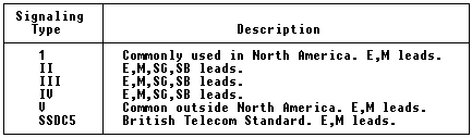
The following chart depicts the the various E and M signaling types. The standard signaling name is indicated in the left-most column.
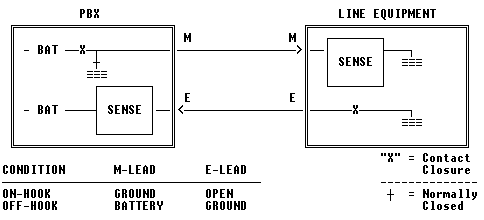
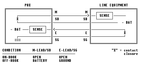
In the Type 1 interface, battery is provided to the transmission equipment on both the E and M leads. NOTE THAT THE VOLTAGE MEASURED ON THE E and M LEADS MAY NOT BE THE SAME (e.g. VDC ON E-LEAD LOWER THAN M-LEAD).
This interface causes high return current through the grounding system. This can even cause problems between two floors of a building if the amount of return current is high enough. This asymmetrical signaling scheme is thought to be a potential source of interference. STILL, THIS IS THE MOST COMMONLY USED 4-WIRE TRUNK SIGNALING INTERFACE IN NORTH AMERICA!
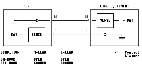
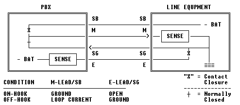
In the Type 5 interface, both the switch and the transmission equipment supply battery. While this interface does not provide isolation between power systems, there is minimal (or none) return currents in this symmetrical signaling scheme. THIS IS THE MOST POPULAR INTERFACE OUTSIDE NORTH AMERICA.
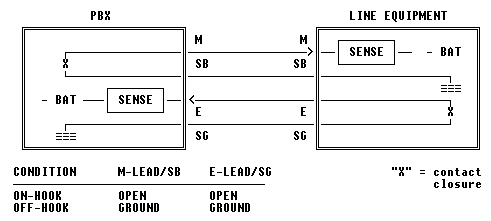
The Type 2 interface provides almost complete isolation of signaling power systems. Along with Type 4 signaling, this interface is LEAST LIKELY to cause interference problems in sensitive environments. IT IS SEEN OCCASIONALLY IN NORTH AMERICA, USUALLY ON CENTREX TRUNK CIRCUITS.
Type 3 signaling is very similar to Type 1, except that the battery and ground source for the M-Lead is supplied by the facility (transmission equipment). Complete power isolation is provided with the M-Lead and the facility can establish and control the amount of E-Lead current. There is no evidence that Type 3’s unbalanced E-Lead has caused any interference problems.
This interface is the most widely used in 1/1AESS, 2/2BESS, and 3ESS switches.
One drawback of this interface is the inability to operate in a “back-to-back” configuration.
The Type 4 interface appears similar to Type 2, with the difference in the operation of the M-Lead. In Type 2, the M-Lead states are OPEN/BATTERY, while for Type 4, the states are GROUND/OPEN. With Type 4, there are no expected fault currents for the M/SB leads. Type 4 is therefore a little bit easier to interface with since accidental shorting (during cable wiring, etc.) of the SB lead will not cause excessive current flow.
A Type 4 interface can interconnect to a Type 2 device. Additionally, the interface can operate in a “back-to-back” configuration.
The only drawback for using Type 4 signaling is that it is difficult to obtain test and supporting equipment for the interface (difficult for an external monitor to distinguish between OPEN/GROUND).
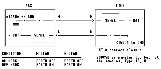
This interface is very similar to Type 5, and can usually be tested using equipment that can support the Type 5 interface. THIS IS WIDELY USED IN THE UK.