| RETURN | Multiplexing |
CCITT International E1 Facilities
The International CCITT framing format is adopted by most countries (Europe, Central/South America, etc.). These facilities operate at 2.048 MBPS.
This framing format is actually defined in CCITT Recommendation G.704, although Recommendation G.732 supplements G.704.
- G.704: Synchronous Frame Structures Used and Primary and Secondary Hierarchical Levels
- G.732: Characteristics of Primary PCM Multiplex Equipment Operating at 2048 KBPS.
G.732/G.704 Framing
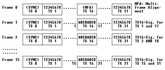
The standard frame is 32 timeslots, with each timeslot consisting of an 8-bit byte. A Multiframe consists of 16 frames, numbered zero to fifteen.
The timeslots are numbered 0 to 31. Timeslot 0 is used for:
- Synchronization
- Alarm Transport
- International Carrier use
Timeslot 16 may be used to transmit Channel Associated Signaling (CAS) information. Note that G.732 DOES NOT define the signaling states, only the transport of the states through the G.732 frame.
However, G.704 recognizes the requirement for Common Channel Signaling and also allows the TRANSPARENT End-To-End transport of Timeslot 16.
Frames 0 through 15:

Timeslot 0 Operation
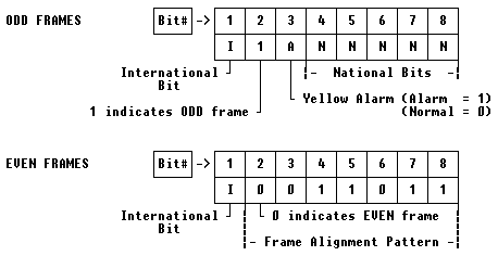
In NORMAL applications, there is NO ERROR CHECKING capability provided within the G.704 specification. In such cases, Timeslot 0 provides the ability to transport International and National bits.
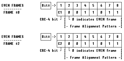
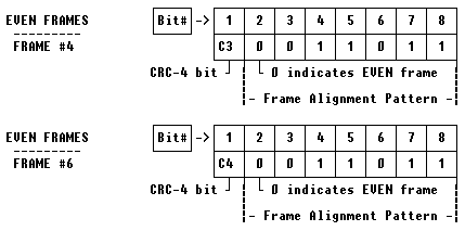
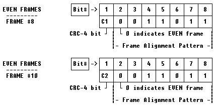
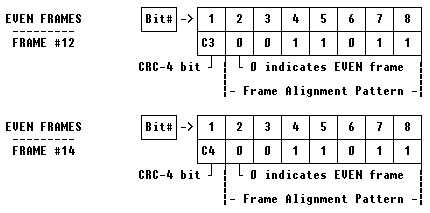
However, G.704 does describe an OPTIONAL implementation where a CRC-4 checksum can be used to provide ERROR DETECTION for Frames 0 through 7, and Frames 8 through 15. When this OPTIONAL format is used, the EVEN FRAME’s International bit is replaced with a CRC-4 bit. The National Bits are relabled as SPARE BITS.
Timeslot 0 Normal Operation (Without CRC-4)
The meaning of the information contained in the Timeslot 0 byte depends upon whether the Frame number is EVEN or ODD:

Timeslot 0 Optional Operation (WITH CRC-4)
As mentioned earlier, a 4-bit Cyclic Redundancy Check (CRC) is used. The CRC bits in Frames 0, 2, 4, and 6 provide error detection for the previously transmitted/received SUB-MULTIFRAME (Frames 0 through 7). The CRC bits in Frames 8, 10, 12, and 14 provide error detection for the previously transmitted/received SUB-MULTIFRAME (Frames 8 through 15):
Timeslot 0 in the Odd Frames:


Timeslot 0 in the Even Frames:


Timeslot 16 Operation
As defined in CCITT G.704, Timeslot 16 MAY or MAY NOT transport Channel Associated Signaling (CAS) information; as mentioned earlier in Section 2 of this document.
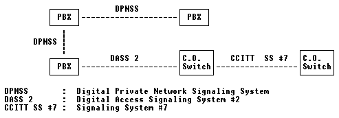
When Common Channel Signaling (CCS) is employed, a digital signaling protocol is used between interconnected equipments. This can be SS7, ISDN, or PBX/Switch Proprietary protocols, as depicted in the following diagram (UK hierarchial application shown):
When Channel Associated Signaling (CAS) is used, ITU recommendation G.732 describes a “MultiFrame” format for the E1 signal:
Frame 0: MultiFrame Alignment Signal
------------------------------------

When Timeslot 16 of the E1 frame is used for Channel Associated Signaling
purposes, Frame 0 contains information that is used by the receiver to
identify the incoming frame.  Specifically, this pattern in Timeslot 0,
Frame 0 is called the MultiFrame Alignment Signal (MFAS).

           |Bit 1 |Bit 2 |Bit 3 |Bit 4 |Bit 5 |Bit 6 |Bit 7 |Bit 8
  Frame 0  |------|------|------|------|------|------|------|------
           |  0   |  0   |  0   |  0   |  X   |  Y   |  X   |  X


           X = Spare Bits, set to 1 if not used.
           Y = Yellow Alarm (Loss of MultiFrame Alignment Signal)
                            (0 = Normal | 1 = Loss of MFAS)


Frames 1-15: Signaling Bits
---------------------------

When Channel Associated Signaling is used, Timeslot 16 of Frames 1-15 is
used to convey the state of the A,B,C and D signaling bits.  Some notes:

   - The ABCD state of 0000 is not allowed. If all bits in Timeslot 16
     are 0, a Loss of MultiFrame Alignment Signal can be assumed.

   - When A-Bit only signaling is used (No BCD bits), the BCD bits
     should be fixed at: B=1, C=0, D=1 (101).


           |Bit 1 |Bit 2 |Bit 3 |Bit 4 |Bit 5 |Bit 6 |Bit 7 |Bit 8
  Frame 1  |------|------|------|------|------|------|------|------
           |Ch 1-A|Ch 1-B|Ch 1-C|Ch 1-D|Ch16-A|Ch16-B|Ch16-C|Ch16-D


           |Bit 1 |Bit 2 |Bit 3 |Bit 4 |Bit 5 |Bit 6 |Bit 7 |Bit 8
  Frame 2  |------|------|------|------|------|------|------|------
           |Ch 2-A|Ch 2-B|Ch 2-C|Ch 2-D|Ch17-A|Ch17-B|Ch17-C|Ch17-D


           |Bit 1 |Bit 2 |Bit 3 |Bit 4 |Bit 5 |Bit 6 |Bit 7 |Bit 8
  Frame 3  |------|------|------|------|------|------|------|-----
           |Ch 3-A|Ch 3-B|Ch 3-C|Ch 3-D|Ch18-A|Ch18-B|Ch18-C|Ch18-D

  .......

           |Bit 1 |Bit 2 |Bit 3 |Bit 4 |Bit 5 |Bit 6 |Bit 7 |Bit 8
  Frame 15 |------|------|------|------|------|------|------|-----
           |Ch15-A|Ch15-B|Ch15-C|Ch15-D|Ch30-A|Ch30-B|Ch30-C|Ch30-D


