| RETURN | Networking |
Introduction
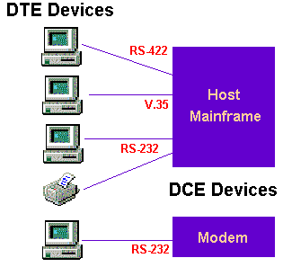
To connect data communications equipment, common electrical interface standards have been developed. There are two sides of an interface:
DTE: Data Terminal Equipment (PC, Terminal, Printer)
DCE: Data Communications Equipment (Modem, Mux, Host/Mainframe)

Interface Specifications
Current Loop
Current Loop interfaces rely on detection of loop current to transmit and receive data. They evolved from the Teletype days of data communications. Although popular through the late 1970s, there is no formal standard for loop current interfaces. Loops generally operated with either 20 mA or 60 mA of current. Loop open conditions were generally considered to be a logic 0, or Space, condition. Loop closed conditions were considered to be a logic 1, or Mark, condition.Current Loop interfaces could easily operate at 9600 baud up to 1500 feet or more. External converters were needed to convert this type of interface to RS-232.
WECO 301/303
The Western Electric 301/303 interface is a Current Loop interface. It is unbalanced interface, capable of operation at high speeds. Typical impedance is 100 ohms. A binary 1 (Mark) is interpreted as a current OFF state; less than 5 mA of current flow. A binary 0 (Space) is interpreted as a current ON state; more than 23 mA of current flow.While this interface used to be popular in the North American Central Office environment, it is rarely seen anymore. The WECO 301/303 interface uses a square, 12-pin Burndy connector.
RS-232
RS-232 is a very popular interface for low speed data signals. It is an unbalanced interface capable of operation from 0 to 20 KBPS at 50 feet. RS-232 is a voltage sensing interface, with the Mark (1) voltage being from -3 to -25 VDC and the Space (0) voltage being from +3 to +25 VDC. Control signals are considered ON when in the voltage range of +3 to +25 VDC. Transmitter impedance values are less than 100 ohms for data and clock signals and less than 1000 ohms for control signals. Receiver impedance is from 3000 to 7000 ohms.The RS-232 interface is implemented in a D-shell connector with 25 pins. It is compatible with interfaces specified in ITU V.24, ITU V.28, and ISO IS2110.
| RS-232 | RS-232 Pinout Information |
V.35
V.35 was originally developed by the CCITT (now the ITU) and is considered obsolete. However, it is still a popular interface for higher speed data signals.V.35 is a balanced interface that senses current flow, versus voltage levels. A Negative Mark (1) is employed; Output A is negative with respect to Output B for a Mark (1). The characteristic impedance is 100 ohms. Voltage levels employed are +/- 1.1 VDC (differential A to B measurement). Driver offset from Signal Ground may be 0 +/- .2 VDC. The Receiver offset from Signal Ground may be as much as 0 +/- .6 VDC. The Receiver sensitivity is +/- 10 millivolts maximum.A word of caution about V.35. It has been obsolete since 1988. It originally specified an electrical data interface capable of operation at 48 KHz at 50 feet. Although V.35 equipment today commonly operates at T1 speeds (1.544 MBPS), there have been cases of incompatibility between devices at the higher bit rates.The V.35 interface is implemented in a square-shell (“Winchester”) connector with 34 pins.
| V.35 | V.35 Pinout Information |
RS-422
RS-422 is a balanced electrical interface capable of operation of T1 speeds or greater. It is most commonly implemented using a D-type connector with 37 pins. The actual connector is specified in the RS-449 specification.A binary 1 (Mark) is represented by the A output being more negative than the B output. A binary 0 (Space) is represented by the A output being more positive than the B output. The receiver can detect transitions with voltage levels of 200 mVDC. A typical impedance of 100 ohms is used and the receiver can have a Signal Ground potential difference of up to +/- 7V and continue to operate properly.
| RS-422 | RS-422 Pinout Information |
RS-423
RS-423 is an unbalanced electrical interface capable of of low speed communications. It is also specified to use the connectors detailed in RS-449.RS-423 transmitters generally operate at +/- 6 VDC and are compatible with RS-232 devices. Receivers are very sensitive, capable of detecting Mark/Space states at +/- 0.4 VDC, allowing compatibility with RS-422 devices. RS-423 has separate Signal Grounds for transmitters and receivers, providing some ground loop protection. A binary one (Mark) is represented by a Negative voltage level and a binary zero (Space) is represented by a Positive voltage level.RS-423 devices operate with the same Ground potential differences as RS-422 and are generally compatible with MIL-STD 188-114, ITU V.10, and RS-232.
MIL-STD
US Military Standards are defined in MIL-STD 188C, MIL-STD 188-100, and MIL-STD 188-114. These interfaces may be either unbalanced or balanced. MIL STD 188C specified a Positive Mark (e.g. binary one is represented by a POSITIVE voltage). MIL STD 188-100 is a Tactical standard similar with MIL STD 188C but using a Negative Mark. MIL STD 188-114 is the current standard, and calls for a selectable Mark/Space voltage to ensure compatibility with either MIL STD 188C or MIL STD 188-100. MIL STD 188-114 recommends the use of a Negative Mark to be compatible with commercial standards-based equipment.MIL STD 188-114 is very compatible with RS-423 except that the Ground potential differences are less than that specified in RS-423. The same rules apply to the Balanced interface, which is compatible with RS-422.The MIL STDs do not standardize a connector, so care must be exercised when interfacing to this equipment.
RS-530
The RS-530 specification is basically the RS-422 and RS-423 interfaces implemented on a 25-pin D-shell connector, as opposed to the 37-pin D-shell specified in RS-449.Either balanced (RS-422) or unbalanced (RS-423) modes are supported. The interface can support Asynchronous or Synchronous transmission rates from 20 KBPS to 2 MBPS. It is compatible with ITU V.10, ITU V.11, X.26, MIL STD 188-114, RS-422, and RS-423.
| RS-530 | RS-530 Pinout Information |