| RETURN | History |
Asynchronous Transmission
Asynchronous transmission was developed and implemented to support the first electromechanical devices, such as teleprinters. Asynchronous characters are output at a rate that is independently generated by the transmitter. The asynchronous characters are actually self-synchronized because they are framed by “Start” and “Stop” bits that delineate the character.
In an idle state, the line is considered to be in a “Marking” state (idle logic “1”s). When a “Space” condition is noted, the receiver is alerted to an incoming character and accepts the data bits. The character is input until the detection of the Stop bit(s). The Stop bit(s), being Marks, serve to return the line to an idle state.
The generator may output the Start bit of the next character at any point in time following the output of the previous character’s Stop bit(s).
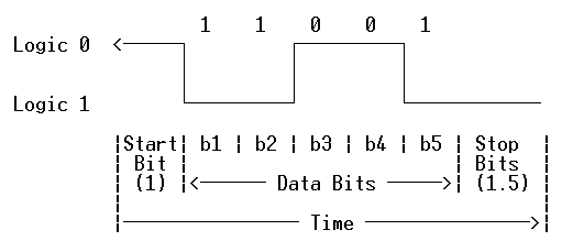
The diagram below depicts a Baudot character, with 1 Start Bit, 5 Data Bits, and 1.5 Stop Bits. The Baudot character is the LTRS “W” or FIGS “2” (depending upon what “case” is active).
 54321
 -----
 10011 (hex 13)
Bit #1 is the Least Significant Bit (LSB) and is transmitted first. Bit #5 is the Most Significant Bit (MSB) and is transmitted last.
.
The diagram above represents a typical oscilloscope display, if a standard Negative Mark interface (RS-232, V.35, RS-422, etc.) is used. The Start bit displays on the left side of the oscilloscope’s screen.
Parity
In the example above, consider an additional bit located between the Stop Bits and Data Bit 5 called the “Parity” bit. For an “Odd Parity” system, this Parity bit would be set to a “0”, because an odd number (3) of ones is present in the character. If the system’s parity is Even then the Parity bit would be set to a “1”, to make to total number of Marks equal to four (4).
Break Characters
When the Break key is depressed on a terminal, a line spacing condition is forced for at least one character length. This is a physical line state, not any defined, recognizable character!
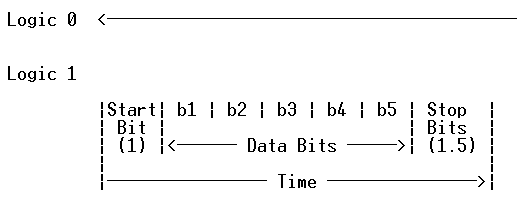
The following illustration depicts a “break” condition for at least one character time. Note that although the Start/Stop bits are shown, they are not really implemented; the bit display is included for illustration and comparison purposes only.

The Break function originated back in the ‘ol teleprinter days, on party-lines or bridged orderwire systems. A short blast of break-condition “chatter” could effectively stop idle chit-chat for “break-in” purposes.
In newer systems, the Break function will usually cause some sort of interrupt on the Host.
Since 4-wire communications systems do not transport the native break condition, some conversions have to take place (e.g. modem to VF signal, etc.), with a suitable deconversion at the receiving site. Therefore, prior to implementing modem systems on hosts that use the Break function, it is necessary to ensure that the communications system can pass the Break function. There may be some incompatibilities between the time it takes a communications network to recognize and transport a Break condition, and the time it takes the Host computer to sense the Break state. As such, practical applications using the Break function aren’t seen much these days!